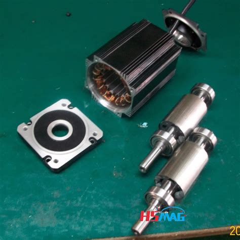
Permanent magnet rotor e1655961736623.jpeg.
1,417 permanent magnets stock photos, 3D objects, vectors, and illustrations are available royalty-free. See permanent magnets stock video clips. Experimental electric generator on white background, consists of copper coils and magnets. A generator is a device that converts mechanical energy to electrical energy for use in an external circuit.
Aug 1, 2022 · The axial lengths of the IPM rotor and the SynRM rotor are respectively changed by changing the parameters L and H. It shows that when the width of the permanent magnet L is 85 mm and the thickness H is 4 mm, the maximum total torque reaches 174.2 N m. The length of the permanent magnet rotor is 141.17 mm. Download : Download high-res image (177KB) Mar 20, 2021 · Reluctance is a function of rotor position in a variable reluctance motor. Sequential switching (Figure below) of the stator phases moves the rotor from one position to the next. The mangetic flux seeks the path of least reluctance, the magnetic analog of electric resistance. This is an over simplified rotor and waveforms to illustrate operation. The nite element results show that the modular rotor permanent magnet ux switching machine has greater torque than salient rotor FEFSM, HEFSM, and PMFSM at the rated load with signicantly less weight than the others. Keywords Back EMF · Electromagnetic torque · Field Excitation · Hybrid Excitation · Modular rotor PMFSM · Permanent magnet The prototype machine is an axial-flux permanent-magnet machine with a two-rotor–one-stator configuration. The nominal power of the machine is 300 W and the nominal rotational speed is 500 rpm. The magnets are neodymium iron boron magnets. Twelve magnets are mounted on the rotor surface and 12 magnets buried on the rotor (Fig. 12a).
The permanent magnet (PM) brushed DC-motor only has one winding: that is of the armature on rotor, whereas the field winding (on the stator) is replaced by a permanent magnet. This is the class of brushed DC-motor that we study in this chapter. PM brushed DC-motors can be found in a wide range of applications.
Magnet Rotors. Magnetic rotor, or permanent magnet rotor is the non stationary part of a motor. The rotor is the moving part in an electric motor, generator and more. Magnetic rotors are designed with multiple poles. Each pole alternates in polarity (north & south). The rotor overtemperature caused by losses is one of the important issues for the high-speed electrical machine. This paper focuses on the rotor loss analysis and CFD-thermal coupling evaluation for 105 kW, 36,000 r/min HSPMSM. Three types of sleeve materials as carbon-fiber, Titanium alloy, and stainless steel are introduced in this paper, …
Electromagnetic interaction between the rotor permanent magnet and the stator slots is quite large. (1000 N simulated value for this motor). The air-gap needs to be as small as 1 mm. Fig. 4a shows the single disc of rotor with 9° skewed permanent magnets. The machine rotors were constructed by using mild-steel.1,417 permanent magnets stock photos, 3D objects, vectors, and illustrations are available royalty-free. See permanent magnets stock video clips. Experimental electric generator on white background, consists of copper coils and magnets. A generator is a device that converts mechanical energy to electrical energy for use in an external circuit.Coaxial counter-rotating propellers have been widely applied in ships and helicopters for improving the propulsion efficiency and offsetting system reactive torques. Lately, the counter-rotating concept has been introduced into the wind turbine design. Distributed wind power generation systems often require a novel approach in generator …To replace permanent magnets on an electric bike rotor, you’ll need a few essential tools: a screwdriver, pliers, and possibly a heat gun. Additionally, gather the …The designed external rotor PMSynRM motor is shown in Fig. 1.PMSynRM is designed to be mounted in the wheels of the EVs. The design parameters of the designed motor are given in Table 1.The d-axis and q-axis magnetization inductances play an important role in determining the electromagnetic performance of the motor [] and this is …
The geometry of one type of internal magnet motor is shown (crudely) in Figure 2. The permanent magnets are oriented so that their magnetizationis azimuthal. They are located between wedges of magnetic material (the pole pieces) in the rotor. Flux passes through these wedges, going radially at the air- gap, then azimuthally through the magnets.
For high-speed permanent magnet synchronous motors (HSPMSM), the rotor eddy current loss is generated by the time and the space harmonics, which results in the rotor temperature rise. This paper deals with the design and analysis of a 100kW, 20000r/min HSPMSM with novel composite rotor. The novel composite rotor includes a shaft, …
This paper presents an analysis of torque pulsation with respect to the rotor rib shape in an interior permanent magnet motors (IPMs) and the type of magnet materials. The effects of three parameters, the angle and length of the flux barrier and the residual flux density of the PM, are studied using the response surface methodology. …The prototype machine is an axial-flux permanent-magnet machine with a two-rotor–one-stator configuration. The nominal power of the machine is 300 W and the nominal rotational speed is 500 rpm. The magnets are neodymium iron boron magnets. Twelve magnets are mounted on the rotor surface and 12 magnets buried on the rotor (Fig. 12a).To solve the problem of tension stress caused by centrifugal force and caused by high-speed operation of permanent magnet (PM) rotor, a FeCo-based PM rotor structure model is proposed. Based on …The geometry of one type of internal magnet motor is shown (crudely) in Figure 2. The permanent magnets are oriented so that their magnetizationis azimuthal. They are located between wedges of magnetic material (the pole pieces) in the rotor. Flux passes through these wedges, going radially at the air- gap, then azimuthally through the magnets. The prototype machine is an axial-flux permanent-magnet machine with a two-rotor–one-stator configuration. The nominal power of the machine is 300 W and the nominal rotational speed is 500 rpm. The magnets are neodymium iron boron magnets. Twelve magnets are mounted on the rotor surface and 12 magnets buried on the rotor (Fig. 12a).
Arnold produces high performance permanent magnet motor components and sub-assemblies for aerospace and defense, industrial, automotive, and motorsport applications, such as: KERS — Kinetic Energy Recovery …Mar 16, 2015 · A post-assembly magnetizing fixture has been designed and successfully used to magnetize the rotor of a 100 kW high speed permanent magnet synchronous motor. The rotor is a solid cylinder with outer diameter of 80 mm and total length of 515 mm. The permanent magnet material is samarium-cobalt (Sm 2 Co 17) with saturation magnetizing field of 6 ... A double-sided permanent magnet rotor with a single stator [2, 3] can offset the axial attraction and increase the output power at the cost of an increased weight. The double-sided permanent magnet rotor design can also reduce bearing wear and noise problem compared with a single-sided structure, which thus increases the generator …Increasing industrial development puts forward high requirements for the performances of stator permanent magnet (PM) machines, such as torque density and efficiency. The paper proposes a new dual stator PM machine based on field modulation theory (DSPMM), which employs the intermediate rotor participating in the …
A high-speed (HS) permanent magnet (PM) synchronous motor (HSPMSM) with a carbon fiber-reinforced plastic (CFRP) protective sleeve in the surface-mounted rotor was explored in this study. In view of retaining the PMs at HS operations, the high-strength CFRP sleeve was designed on the basis of a process that could be summarized as …Harmonic Distortion is very low at <2% giving superior waveform, meaning that our low rpm permanent magnet generators help you guarantee the safe operation of modern sensitive electronic equipment. When using our low rpm pmg generators, power density is increased using inverter technology, where the traditional excitation winding systems are ...
In this work, different analytical methods for calculating the mechanical stresses in the rotors of permanent magnet machines are presented. The focus is on interior permanent magnet machines. First, an overview of eight different methods from the literature is given. Specific differences are pointed out, and a brief summary of the …Aiming at the rotor strength problem of high speed permanent magnet synchronous motor (HSPMSM), a design method for maximum outer diameter of permanent magnet is proposed. Firstly, on the basis of mechanics of materials, the stress analytical model of HSPMSM rotor with anisotropic material is established. Then, the …Permanent-magnet fields are, by definition, constant and not subject to failure, except in extreme cases of magnet abuse and demagnetization by overheating. Although PM motors are more expensive than induction motors, they offer a longer operating life, improved efficiency, better thermal resistance, reduced size and weight.A stationary magnetic field is produced across the rotor by poles on the stator. These poles may be encircled by field coils carrying direct current, or they may contain permanent magnets. The rotor or armature consists …effects of magnet polarities [18,19], PM number [20], winding configurations[21,22], asymmetrical stator pole [23], stator/rotor combinations [24] etc., and their effects on electromagnetic characteristics have been presented. Further more, investigations of the working mechanism have demonstrated that only fundamental rotor permeance andIt should be understood that the “rotor inside” vs. “rotor outside” distinction is in fact trivial, with very few exceptions, which we will note. 2.1 Surface Magnet Machines Figure 1 shows the basic magnetic morphology of the motor with magnets mounted on the surface of the rotor and an otherwise conventional stator winding. Non−Magnetic Rotor Core Rotor Magnets Rotor Pole Pieces Figure 2: Axial View of a Flux Concentrating Motor The geometry of one type of internal magnet motor is shown (crudely) in Figure 2. The permanent magnets are oriented so that their magnetizationis azimuthal. They are located between wedges of magnetic material (the pole pieces) in …Rotor configurations strongly affect the torque and efficiency performance of permanent magnet electric motors. In this paper, different rotor configurations of the permanent magnet BLDC motor ...Permanent-magnet fields are, by definition, constant and not subject to failure, except in extreme cases of magnet abuse and demagnetization by overheating. Although PM motors are more expensive than induction motors, they offer a longer operating life, improved efficiency, better thermal resistance, reduced size and weight.Purpose This paper comprehensively analyses the radial electromagnetic (EM) force by unit area and vibration characteristics in a permanent magnet synchronous motor (PMSM). This provides the possibility to verify the action law, causes, and influencing factors of vibration deformation and provides new ideas for vibration management. …
Rotor configurations strongly affect the torque and efficiency performance of permanent magnet electric motors. In this paper, different rotor configurations of the permanent magnet BLDC motor ...
In this study, a three‐phase outer rotor PMaSynRM with a power of 1 kW and a speed of 750 rpm was designed. The stator and rotor geometric structures of the designed motor were determined. The combination of slots/poles …
2.1 Electrical Characteristics. The equivalent circuit of a PMDC motor is shown in Fig. 1. The supply voltage and the current are given. The circuit consists of an induced voltage (Vi) in series with an armature resistor (Rarm) and inductance (Larm). The rotation of the ux generates the induced voltage. When the rotor magnets are placed inside the rotor iron in PMSM, the machine is called interior permanent magnet (IPM) . In this case, the magnetic reluctance is not uniform as it was for SM-PMSM. So, the self-inductance value of the stator will depend on the rotor position and, consequently, there will be nonzero reluctance torque in addition to the …More specifically, the rotor itself contains permanent magnets, which are either surface-mounted to the rotor lamination stack or embedded within the rotor …The eccentricity of the rotor influences the gap permeance, the operating point of the rotor magnets, the gap magnetic flux density distribution, and therefore the electromagnetic force and its spectral distribution. In this paper, the NVH response for dynamic and static eccentricities based on the radial magnetic force harmonics is …Aug 1, 2022 · The axial lengths of the IPM rotor and the SynRM rotor are respectively changed by changing the parameters L and H. It shows that when the width of the permanent magnet L is 85 mm and the thickness H is 4 mm, the maximum total torque reaches 174.2 N m. The length of the permanent magnet rotor is 141.17 mm. Download : Download high-res image (177KB) 2.1 Electrical Characteristics. The equivalent circuit of a PMDC motor is shown in Fig. 1. The supply voltage and the current are given. The circuit consists of an induced voltage (Vi) in series with an armature resistor (Rarm) and inductance (Larm). The rotation of the ux generates the induced voltage.Axial-flux permanent magnet (AFPM) motors have been attracting great interest due to their key advantages of high-torque density and compact structure. Concentrated windings are commonly used for AFPM motors since they significantly reduce the radial length of the end windings. This paper proposes a novel double-sided stator …It should be understood that the “rotor inside” vs. “rotor outside” distinction is in fact trivial, with very few exceptions, which we will note. 2.1 Surface Magnet Machines Figure 1 shows the basic magnetic morphology of the motor with magnets mounted on the surface of the rotor and an otherwise conventional stator winding. Jul 30, 2022 · In this paper, an improved rotor position observer with sliding mode control strategy of permanent magnet synchronous motor was studied. A MPF was designed instead of LPF to reduce the chattering in the traditional SMO back EMF and eliminate the system phase delay.
The windings of coreless axial flux permanent-magnet machine (CAFPM) are exposed to the rotor magnetic field, where each back electromotive force (EMF) harmonic is induced not only by several ...In this paper, an optimal design procedure which includes multi-physics analysis to design the multi-phase external rotor PMa-SynRMs is presented. In specific, a five-phase external rotor PMa-SynRM with neodymium based magnets has been proposed as a solution to produce higher power density compared to the conventional internal rotor PMa-SynRMs ...Magnetic rotors from Sintex a/s are highly efficient high-quality rotors. The advantages of choosing Sintex® magnetic rotors are as follows: Patented solutions; Complete …Instagram:https://instagram. comfortview womenpercent27s wide widthi 75 rest areas in kentuckybaro kim213ad k8 This paper proposes a new design method for sleeve thickness and interference based on a multi-dimensional visualization algorithm that overcomes difficulties in solving. The contact pressure between the rotor core and the permanent magnet, the maximum equivalent Mises stress of the permanent magnet, and the maximum …When the rotor magnets are placed inside the rotor iron in PMSM, the machine is called interior permanent magnet (IPM) . In this case, the magnetic reluctance is not uniform as it was for SM-PMSM. So, the self-inductance value of the stator will depend on the rotor position and, consequently, there will be nonzero reluctance torque in addition to the … used subaru crosstrek under dollar15000heidi klumpercent27s halloween costumes The accurate calculation and reduction of electromagnetic force waves are important prerequisite for the evaluation and optimization of electromagnetic vibration. In this paper, an accurate calculation method of air gap permeance is proposed, the air gap flux density and the resulting electromagnetic force waves of 6p36s surface-mounted …This paper proposes a two-phase radial flux brushless DC motor comprising a rotor decorated with hybrid permanent magnet (PM) material, i.e., rare-earth NdFeB magnets combined with ferrite magnets. The rare-earth NdFeB magnets are used on the surface, and ferrite magnets in the spoke-type configuration. The combined surface and … eurobos zeus_2 High-speed or ultra-high-speed permanent magnet synchronous motors (PMSMs) have a strong trend of application in modern industry due to those simple structures and high power density. 1,2 For high-speed motors or generators, the rotor speed is normally above 30,000 r/min even may exceed 100,000 r/min. Designs of such high …Rotor configurations strongly affect the torque and efficiency performance of permanent magnet electric motors. In this paper, different rotor configurations of the permanent magnet BLDC motor ...addition to the magnet torque, thus improving the efficiency. In addition, the IPMSMs provide more rotor robustness as magnets are embedded in the rotor laminations; hence, no additional retention sleeving is required. Various IPMSM technologies have been studied in the literature. In [3], the V-shape, the U-shape, the spoke-type and the